Sunday, March 17, 2013

Voltage Dividers

The design of our voltage dividers consists of three load resistors of equal resistances connected parallel and powered by an unregulated power supply. Each load can be switched on or off such that we exhibit an upper and lower bound voltage and resistance. It should be intuitive that closing a switch will give us the maximum equivalent resistance and closing all three switches will give us the minimum resistance. We needed to find the resistance for the shunt resistor (RS) to prevent the system from short circuiting. Our calculated value for Rwas 45.05 Ω and thus our voltage source needed to run at 6.53 V. From these values, we further determined our current (IBUSwith the maximum equivalent resistance was 6.25 mA and 17.2 mA for the minimum equivalent resistance.


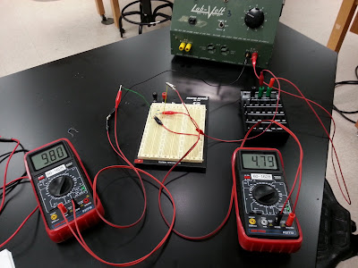
Our setup consisted of a resistor box as the shunt resistor and the three parallel load resistors at 1000 Ω each, wired to the breadboard, all connected in series. An ammeter was connected in series with the system to measure IBUS and a voltmeter is connected parallel to the load resistors to measure VBUS.

Our data goes as follows:

1 Load
Req = 9.79 Ω
VBUS = 5.49 V
IBUS = 5.65 mA
PLoad = 0.0312 W


2 Loads
Req = 489 Ω
VBUS = 4.75 V
IBUS = 9.80 mA
PLoad = 0.0470 W


3 Loads
Req = 326 Ω
VBUS = 4.25 V
IBUS = 13.19 mA
PLoad = 0.0567 W

PLoad can be calculated as
PLoad IBUSReq

The actual percentage in load voltage variation was 9.8% and 15.0% up and down, respectively. The variations in the values of the resistance box and the load resistors differed from their true respective values enough to cause a discrepancy.

By adding a fourth 1 kΩ resistor parallel to the circuit, and assuming the shunt resistance and voltage supply remains the same, the new load voltage was calculated to be 5.525 V.

If we wanted to reduce the load voltage variation to ±1% for the 3-load case, our source parameters would have to be V= 5.05 V and R= 46.2 Ω.

No comments:

Post a Comment